Hardware Setup#
BAM’s identification pipeline requires a pendulum test bench with variable loads and lengths to increase the variety of the collected logs. The pendulum is attached directly to the actuator’s output shaft, optionally using a counter-shaft when the actuator supports it.
To present the identification process, the Dynamixel XL-330 motor is used as a case study. The instructions are similar for other actuators, adjusting only for the mass and length parameters.
Requirements#
The hardware required for the identification process is as follows:
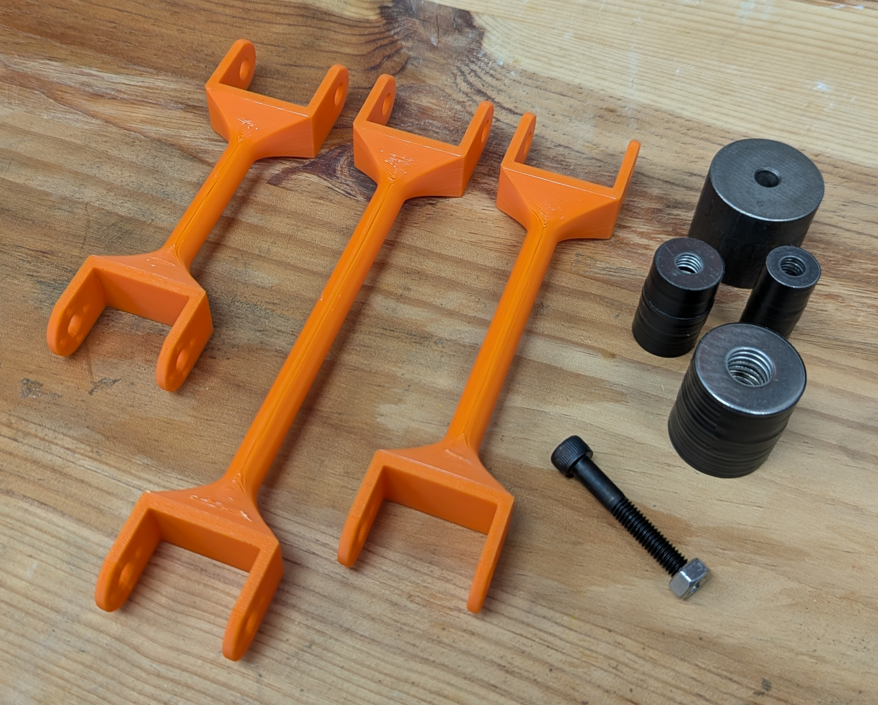
A set of rigid arms of varying lengths.
The mass of the arms should be negligible compared to the attached loads. Therefore, it is recommended to use 3D-printed or laser-cut wooden arms for smaller motors handling light loads, and to reserve metal arms for more powerful motors.
A set of weights compatible with the arms.
The masses must be heavy enough to generate a wide range of load torques.
A mounting bracket for the actuator.
The setup must ensure that the actuator remains firmly secured during data logging, despite the fast movements of the weights at the end of the arm. The arm-weight assemblies must have sufficient clearance to oscillate between +/- 90° relative to the vertical position.
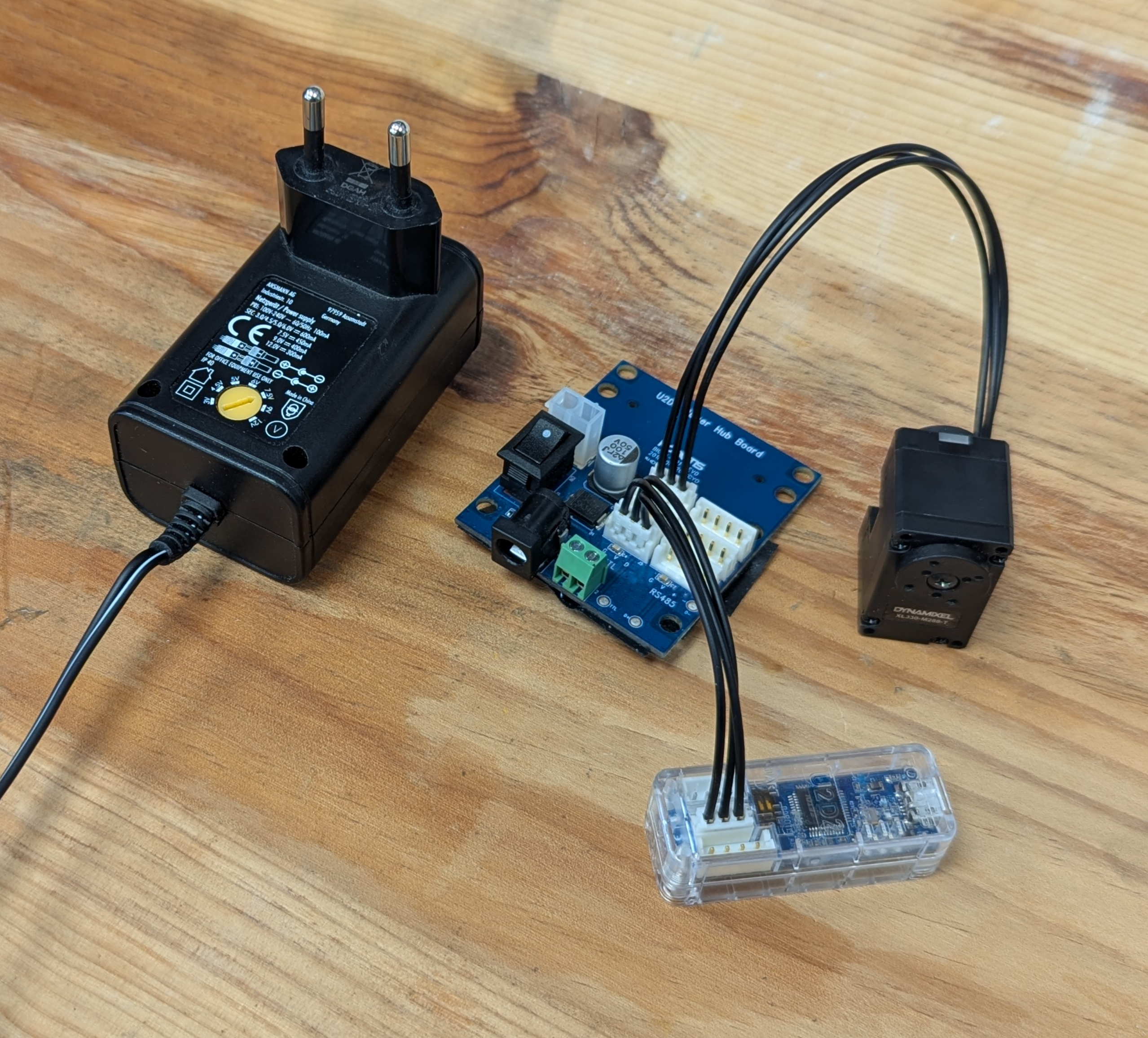
A communication interface for the actuator.
Once the hardware is gathered, you must record the mass of the weights as well as the length and mass of the arms. These parameters are mandatory for the identification process.
Example: Dynamixel XL-330#
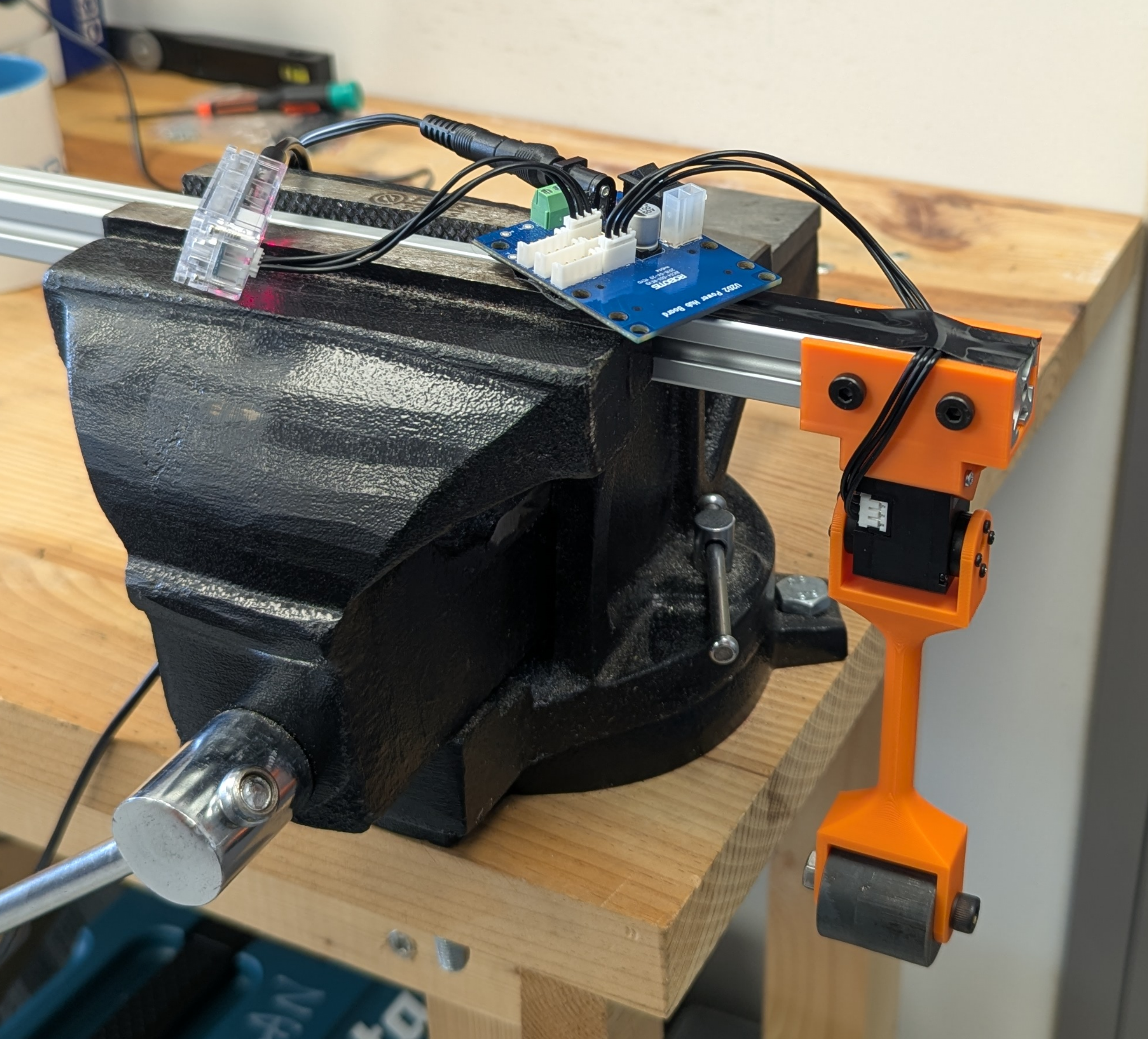
Here is an example of a test bench for the Dynamixel XL-330 actuator. The pendulum arms are 3D printed; you can refer to the 3D model for inspiration here.
The interface with the actuator is established using a U2D2 kit.
The complete setup is shown below. The pendulum is attached to the actuator’s output shaft, and the masses are fixed to the end of the pendulum arm.